Circuit Diagram Of An Alternator
5. Connect the W Terminal. The W terminal is used for the alternator warning light or gauge. Connect this terminal to the warning light or gauge for proper monitoring of the alternator's performance. 6. Connect the Ground Terminal. Lastly, connect the ground terminal to a suitable ground point on the vehicle's chassis.
Wiring Diagram 1 Wire Alternator Wiring Diagram and Schematics
Hey Guys ! Today, i will be sharing some basic info about the terminal connections of an alternator with full explanation about its working of it field (rot.
33 Cs130d Alternator Wiring Diagram Wiring Diagram Info
3 Wire Alternator Wiring Diagram. This is a three-wire alternating wiring diagram showing the connections between the different components of a circuit. The circuit comprises three main wires: battery positive cable, voltage sensing wire, and ignition wire. The ignition input wire is attached to the engine.
Wiring A Alternator To Battery
Need Help? Ask a mechanic online, 24 hours a day here: https://tinyurl.com/24-7-mechanicIn this video we'll talk about a 3 wire alternator wiring diagram, ho.

Lucas 18 Acr Alternator Wiring Diagram
3 Wire Alternator Wiring Diagram. This three-wire alternating wiring schematic demonstrates the connections between the various circuit parts. The three main wires that make up the circuit are the battery's positive cable, voltage sensor, and ignition input wire. There is also a connection between the engine and the ignition input wire.
Gm Single Wire Alternator Wiring Diagram
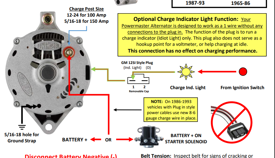
Alternator Wiring Kit 555 -10510 100 Amps 8 gauge 150 Amps 6 gauge 200 Amps 4 gauge It is very important to use the correct wire size to connect the alternator to the battery. A wire size too small can allow the wire to overheat, melt the insulation and cause a fire or worse..

Marine Alternator Wiring Diagram EdenBengals
Wiring an alternator warning light is fairly straightforward, and the procedure is the same regardless of the car or truck you're working on. In this article, we'll discuss the basics of wiring an alternator… Read More ». Types of Wiring Diagrams When it comes to wiring diagrams, there are two main types: schematic diagrams and.

Alternator Wiring Diagram 2 Wire
A typical 3-wire alternator wiring diagram with an internal voltage regulator. Computer-Controlled Voltage Regulation. Many late-model vehicles use the engine computer, which is often referred to as the powertrain control module (PCM), to control alternator output. Most modules use an internal driver to turn the alternator's field circuit on.
thermo king apu alternator wiring diagram
Step 4: Electrical Connections. Connect the brushes of the positive red cable to the alternator's positive terminal. Then, connect the negative terminal of the brush (it may be blue or black) from the rotor field to any part of the alternator's casing (as the ground). Wiring diagram for a 1-wire alternator.

Wiring Diagram Automotive Alternator
2 wire alternator wiring diagram. A 2-wire alternator has three connections, the first being the ground. This connection is also called the output connection. It allows power to flow through the alternator and other components of your car. The second connection is the positive (possibly fuseable) terminal and is connected directly to the battery.

Technical Understanding alternator wiring The H.A.M.B.
Step #1 Disconnect the battery! Always do this step! Step #2 Locate the voltage regulator, usually on the firewall. Remove the ARM and FLD wires and tape them back with electrical tape in case you or the next guy want to re-install a generator. These wires connect to the generator and you don't need them. Step #3 Remove the 2 wires from the.

Everything You Need To Know About Alternator Wiring Diagrams WIREGRAM
9 - If installing an alternator with OEM wiring connections, reconnect alternator wires and battery ground cable. If installing a 1-wire alternator, see wiring instructions at upper right. 10 - Make sure battery is fully charged before starting engine. 11 - Reconnect the ground cable, start the engine and using a VOM meter, verify that the.
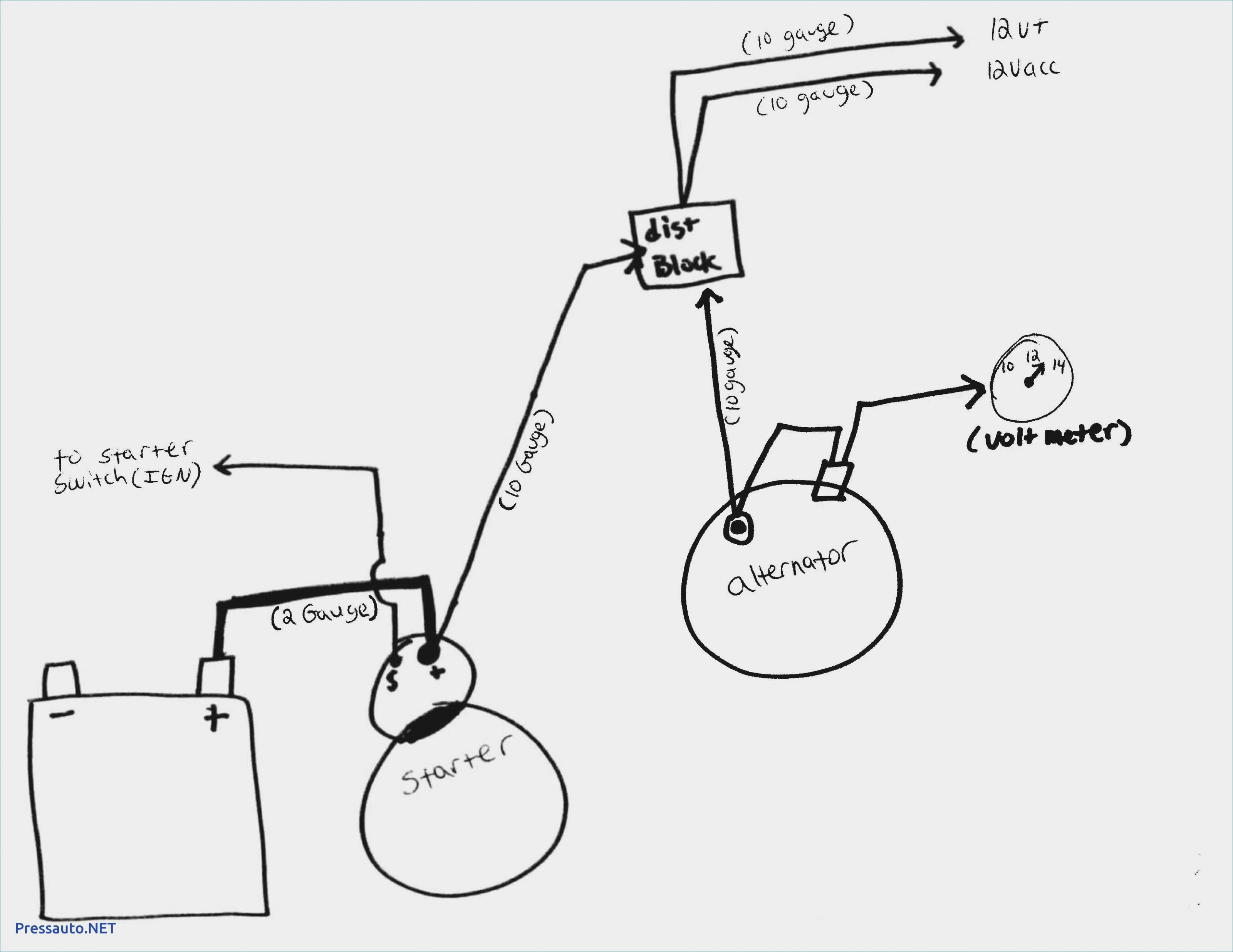
Wiring Diagram Alternator To Battery Wiring Diagram
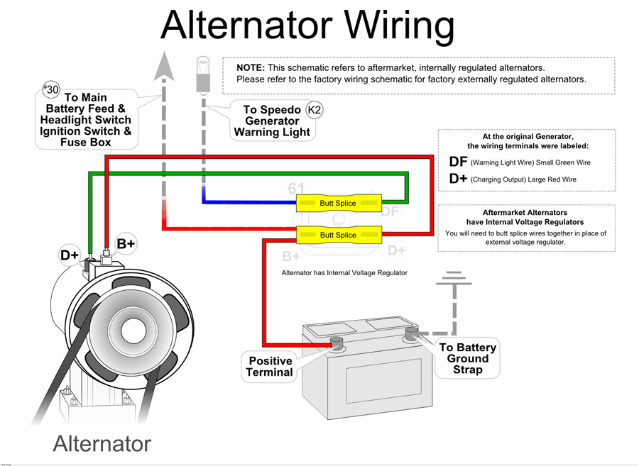
3-wire alternator Wiring Diagram . Most people refer to a standard General Motors alternator with an integrated regulator as a 3-wire alternator, often known as a 3-pin alternator. It is an upgrade over the 1-wire variety and may be installed in earlier vehicles. The voltage at the fuse box and the ignition are monitored by the 3-wire.
Leece Neville Alternators Wiring Diagram Wiring Diagram
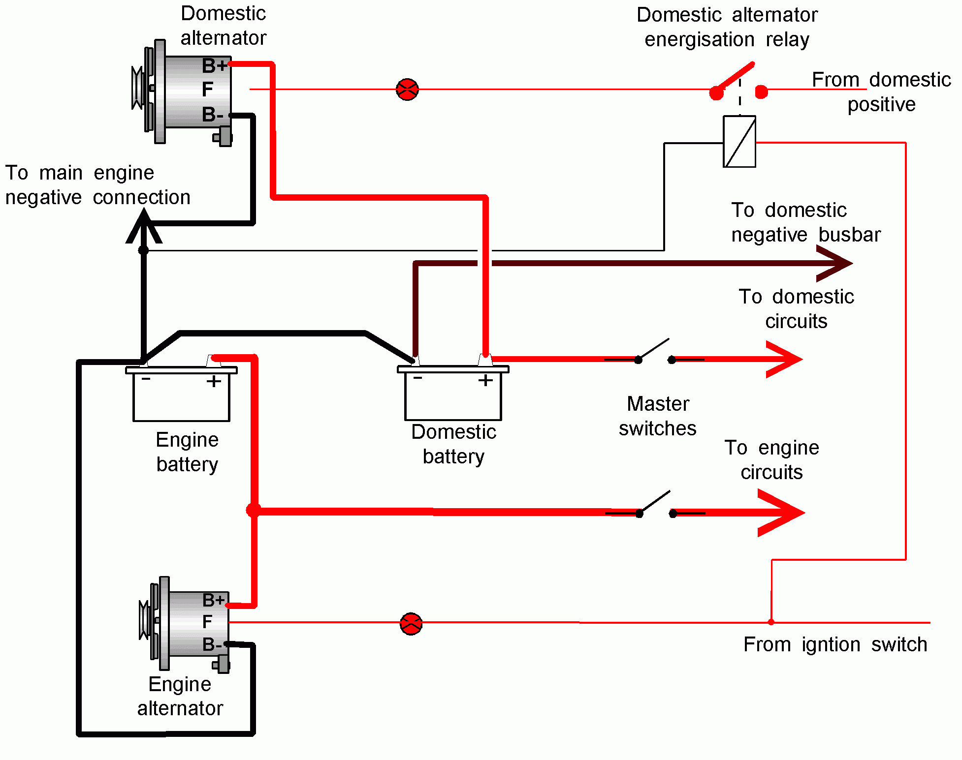
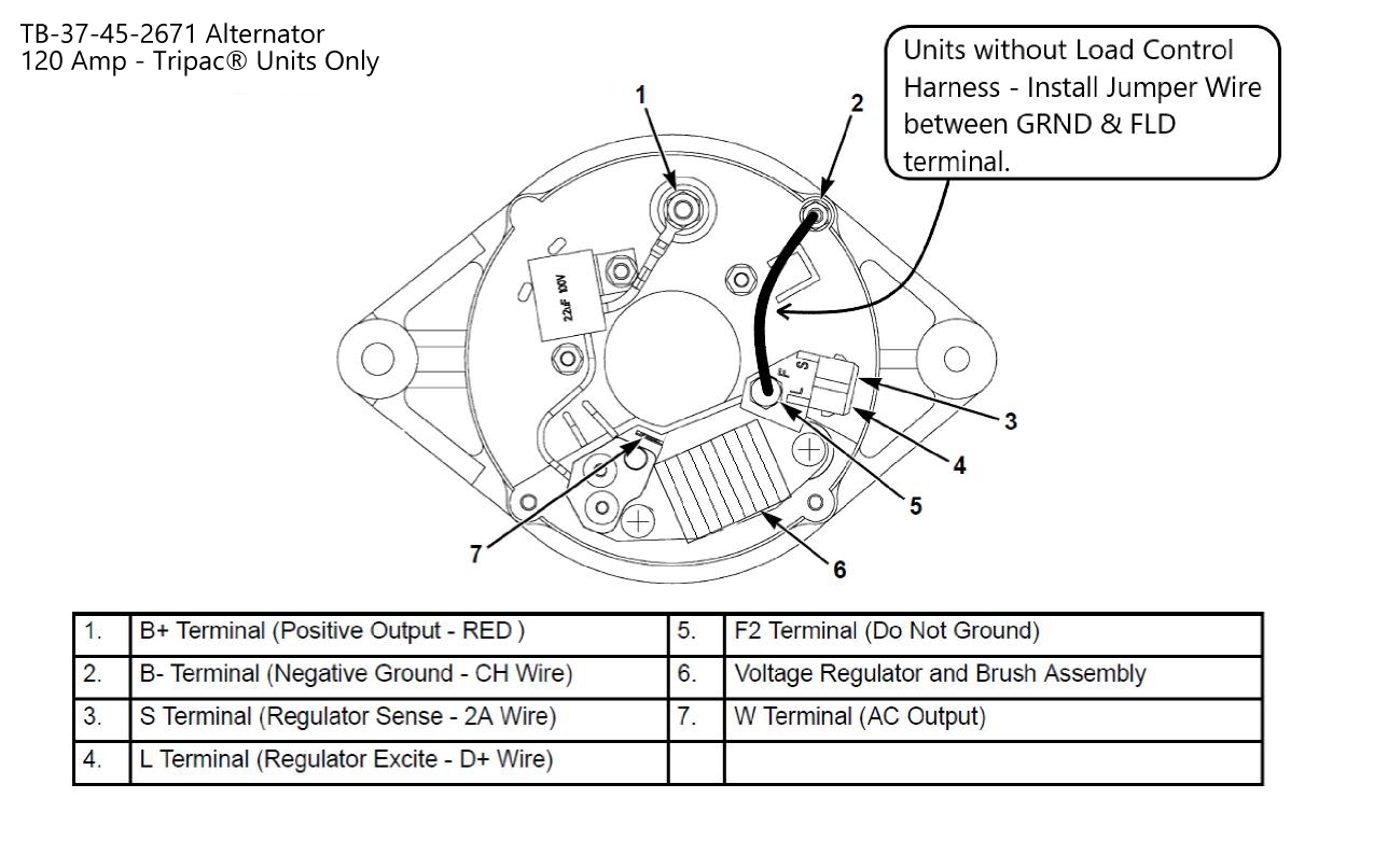
Four wires connect the alternator to the rest of the charging system. B is the alternator output wire that supplies current to the battery. IG is the ignition input that turns on the alternator/regulator assembly. S is used by the regulator to monitor charging voltage at the battery. L is the wire the regulator uses to ground the charge warning.
Aro Wiring Diagram Wiring Library Chevy Alternator Wiring Diagram Wiring Diagram
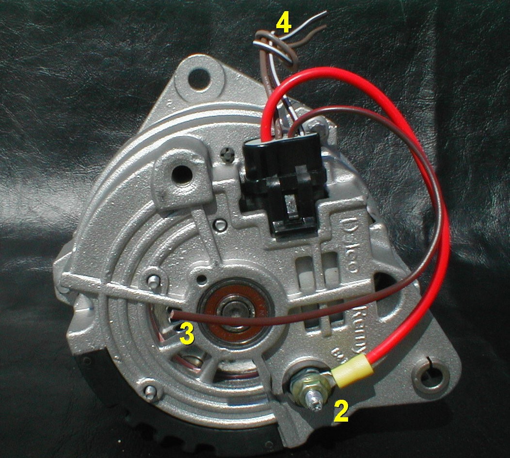
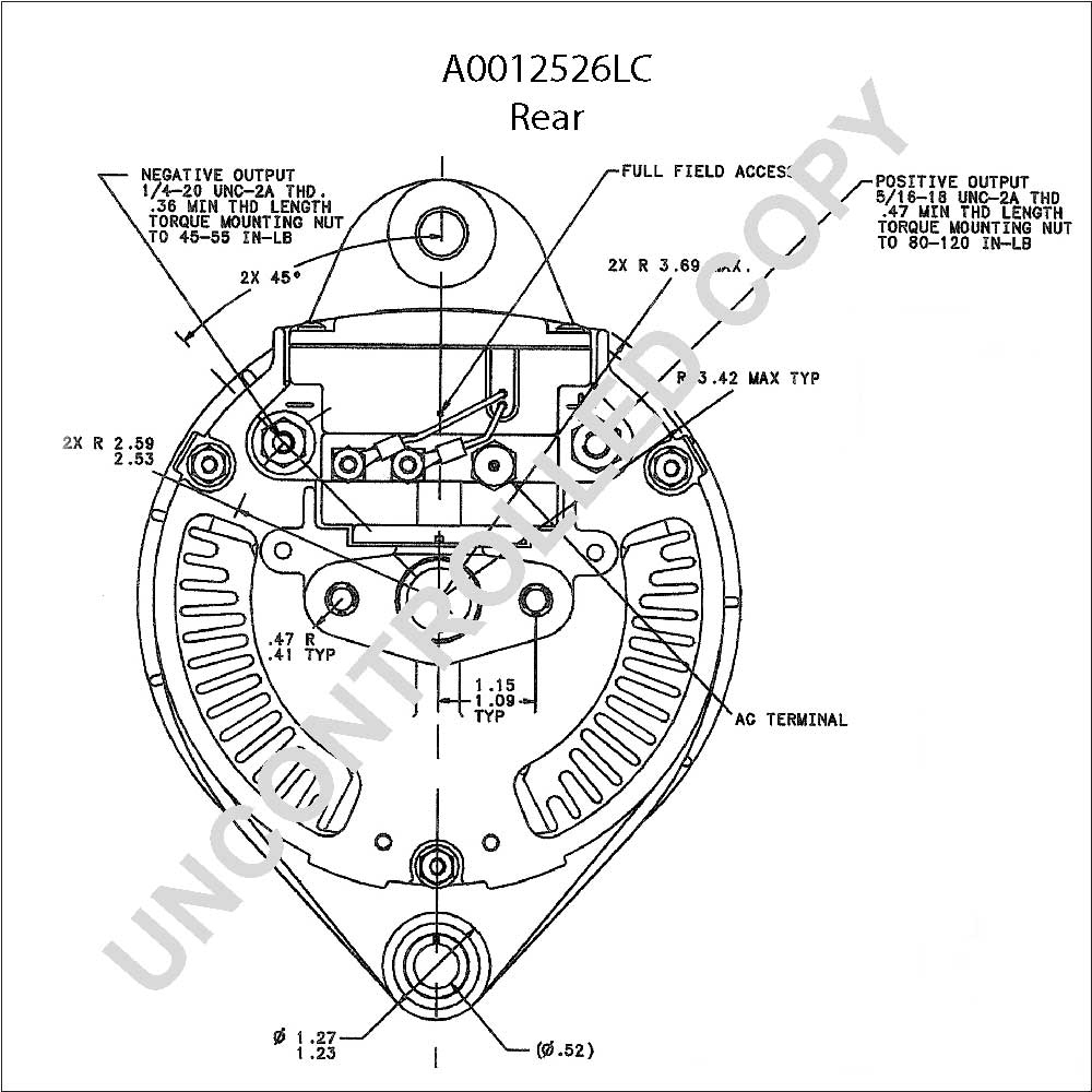
So if your alternator housing is unmarked, look from the rear of the alternator: the #1 terminal is on the left and the #2 on the right. You only need an ignition wire to the #1 terminal to make an Si series alternator work. The #2 terminal is for voltage sensing, and is optional. The #2 voltage sensing terminal allows the voltage regulator to.

12 Volt Alternator Wiring Schematic Free Wiring Diagram
4 Wire Alternator Wiring Diagram is the linchpin of a vehicle's electrical system, seamlessly connecting components from the GM to Delco. It ensures an efficient conversion of alternating current from the alternator to direct current for your battery, harmonizing the electrical demands of any car, whether Ford or Chevrolet.