Poe Rj45 Pinout Diagram Wiring Diagram Poe Ip Camera Wiring Diagram
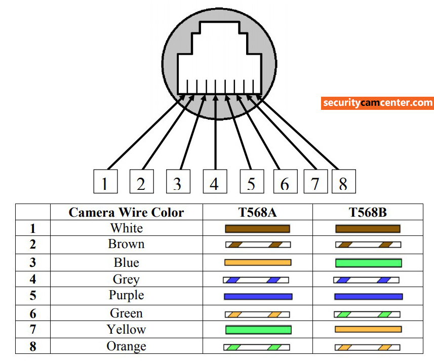
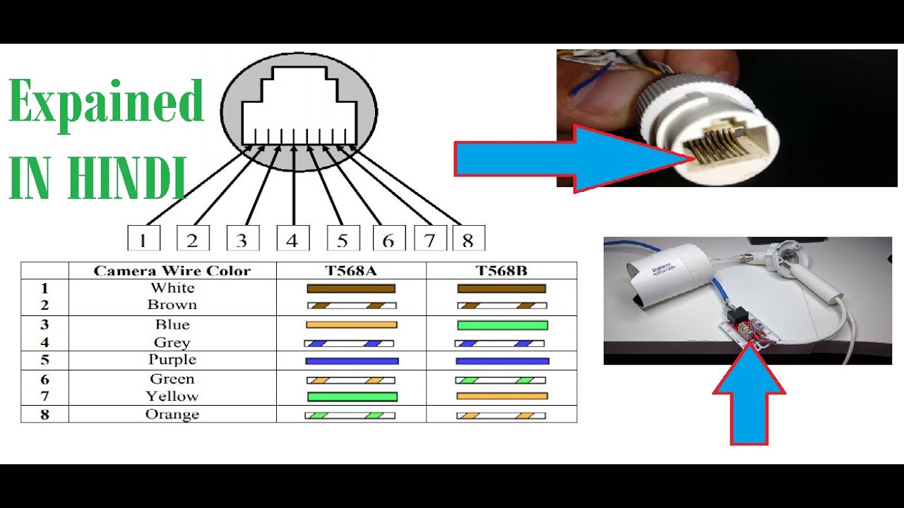
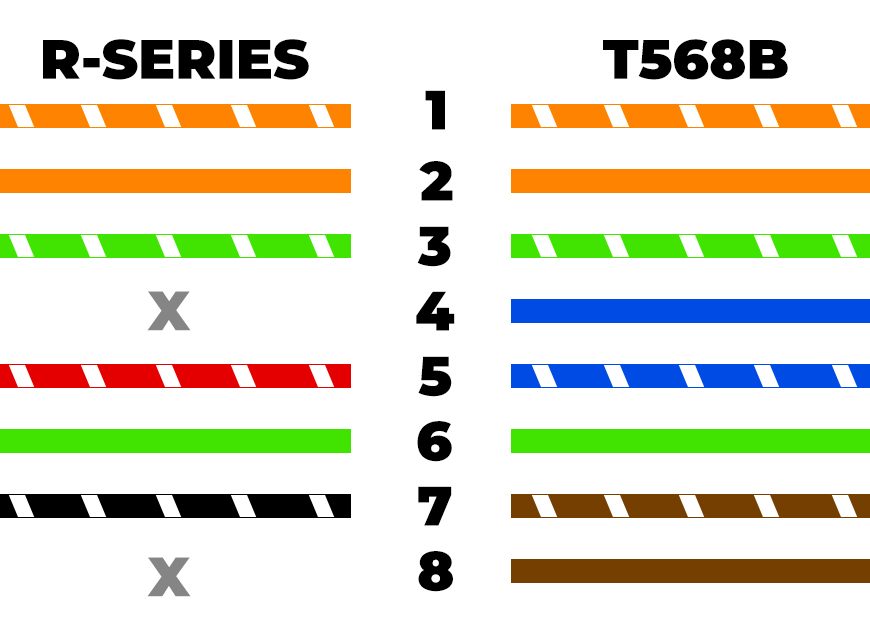
Take a look at the picture below, on the left side it's the RJ45 pinout (T-568B) and the right side the Dahua IP camera PoE pinout (color coded wiring diagram). Make the connection as shown on the illustration. For example, grey wire goes to pin 8, brown wire goes to pin 2, blue goes to pin 1 and so on.
Hikvision IP Camera RJ45 PinOut (wiring) —
An IP camera wiring diagram is a diagram that shows how the IP camera is wired to the security system. The diagram shows a visual representation of the wiring from the camera to the security system, including cables, power supplies, and other connection points.
kop logboek hoog hikvision camera rj45 pinout taart Los Ellende
Reolink RLC-410W WiFi CCTV network diagram (When the WiFi IP camera network setup is done, you are free to remove the Ethernet cable.) Reolink RLC-410 PoE IP camera network diagram. Reolink Argus 2 wire-free IP CCTV network diagram Battery powered cameras link to the router wirelessly by scanning a QR code containing all the WiFi information.

Ip Camera Pinout Wiring Diagram Easy Wiring
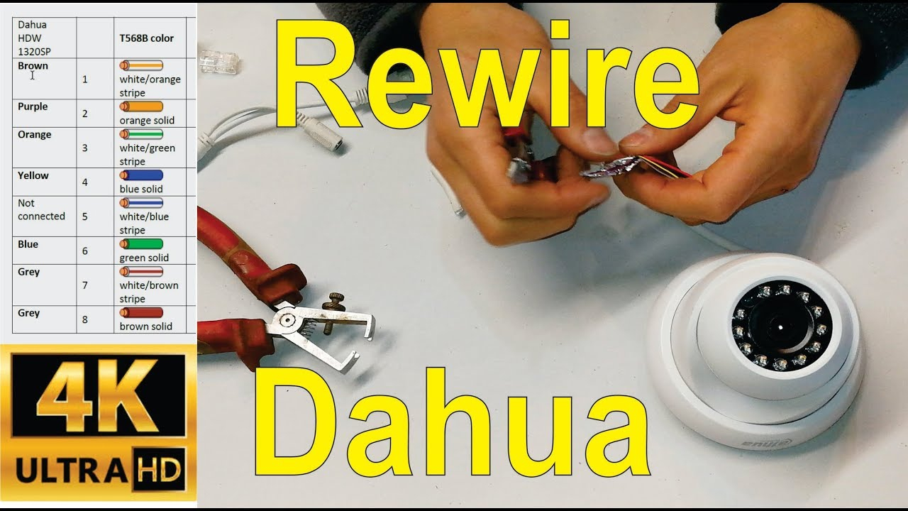
For instance, Brown is pin 1, Purple is pin 2, Orange is pin 3, Yellow is pin 4, and so on. Here is everything that you have to know if you want to wire a damaged Dahua IP camera cable: Aside from the example that you can see above, a lot of Dahua IP cameras can have a different pinout diagram.
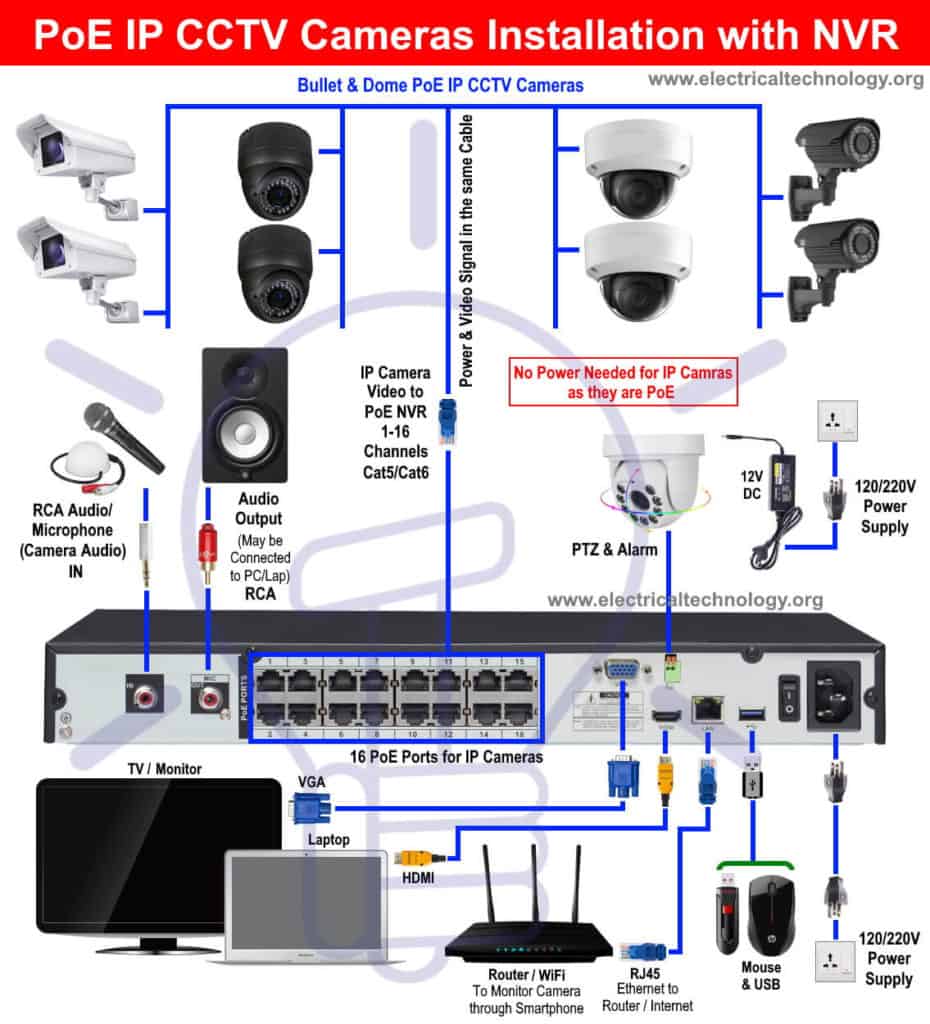
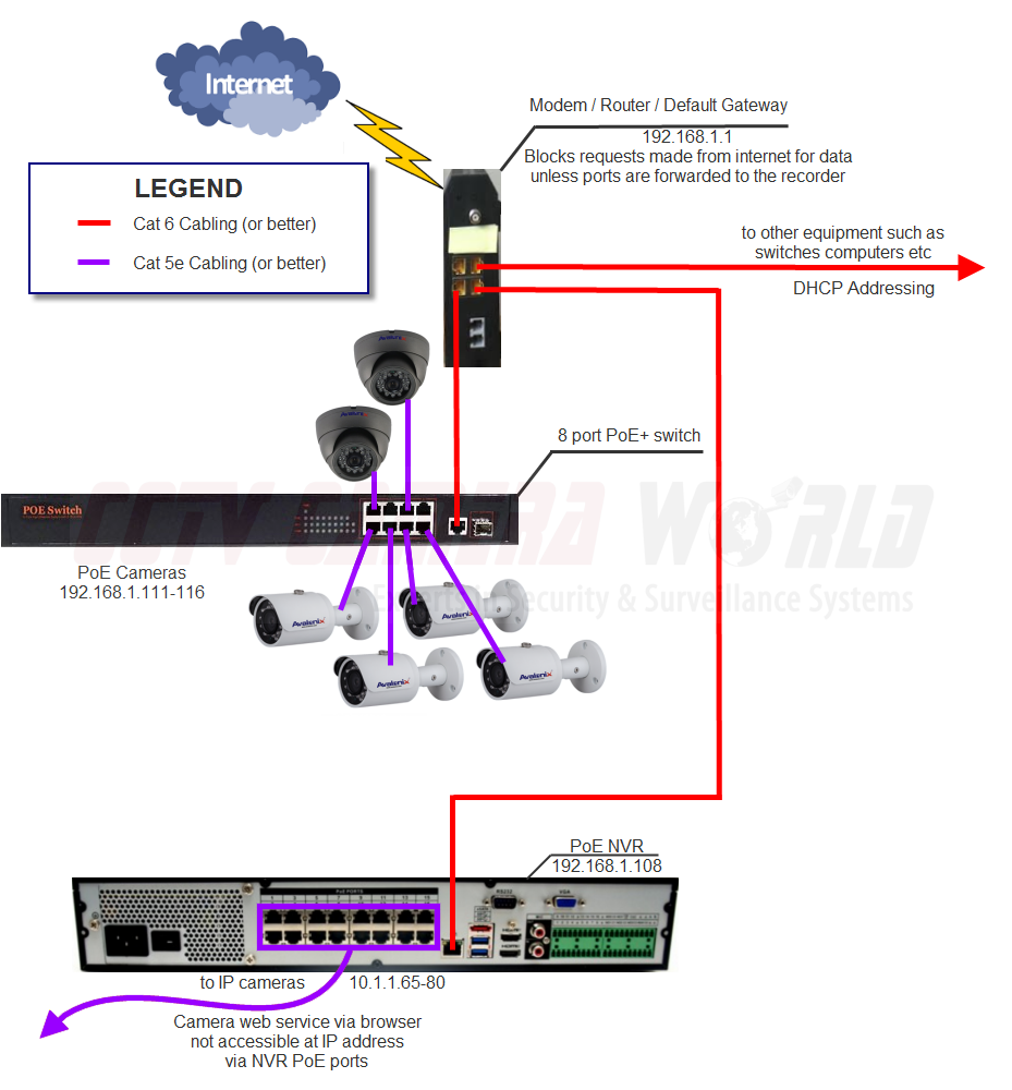
How to Install PoE IP CCTV Cameras with NVR Security System
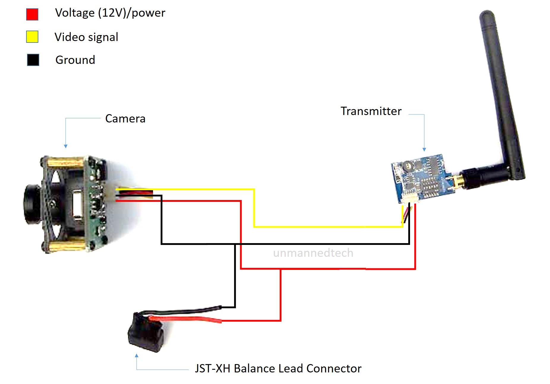
Below is a description of the basic functionality of each wire associated with the Ethernet port pins these cameras: Cameras with external mic/speaker output wiring, such as the IP8M-2493E, etc, the diagram may be different. Please refer to the information below for more details
How to Reuse Hikvision IP Camera After Burn and Damage Connector Part 1
In the constantly evolving world of surveillance technology, IP cameras have become an indispensable tool. To unlock their full potential, understanding the pinout wiring diagram is crucial. This intricate diagram serves as a roadmap, guiding technicians through the labyrinth of wires that connect these cutting-edge devices. Brace yourselves, as we embark on an electrifying adventure into the.

Bisschop Slepen Veraangenamen hikvision ip camera rj45 pinout Algebra
32 posts Posted January 12, 2014 Anyone out there have the color code/pinout for the Ethernet port on an IPC-HFW2100 IP camera? The POE Ethernet port for my IP camera is damaged and missing a pin. I want to replace the port with a standard RJ45 keystone jack. If I knew the color code and pinout for the camera I could do this.
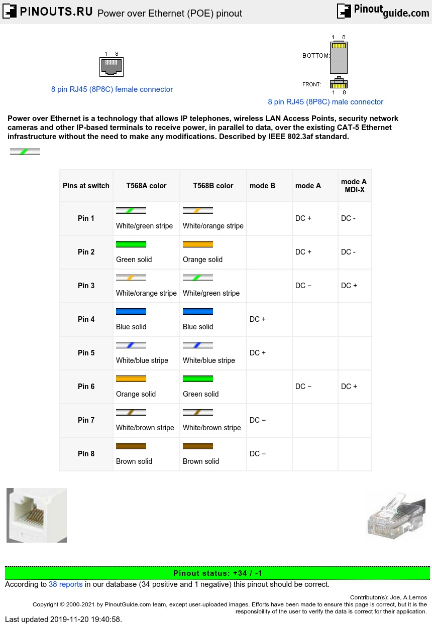
Power Over POE Pinout Diagram Pinoutguide 13400 Hot Sex Picture
A Hikvision IP camera wiring diagram is chiefly composed of two components: an electrical diagram and an IP camera architecture diagram. The electrical diagram contains information about how the connections between the cameras and other networking equipments are established.
Cat 6 Poe Camera Wiring Diagram Dahua Ip Camera Color Code Pinout For
To ensure the camera is correctly connected and powered, understanding the basics of IP camera wiring diagrams and pinout diagrams is key. A pinout diagram maps the pins of a device to the wires that connect it to other devices or to a power source. This type of document is incredibly useful for troubleshooting and diagnosing issues with an IP.

Ip Cameras Wire Diagram Manual EBooks Poe Ip Camera Wiring Diagram
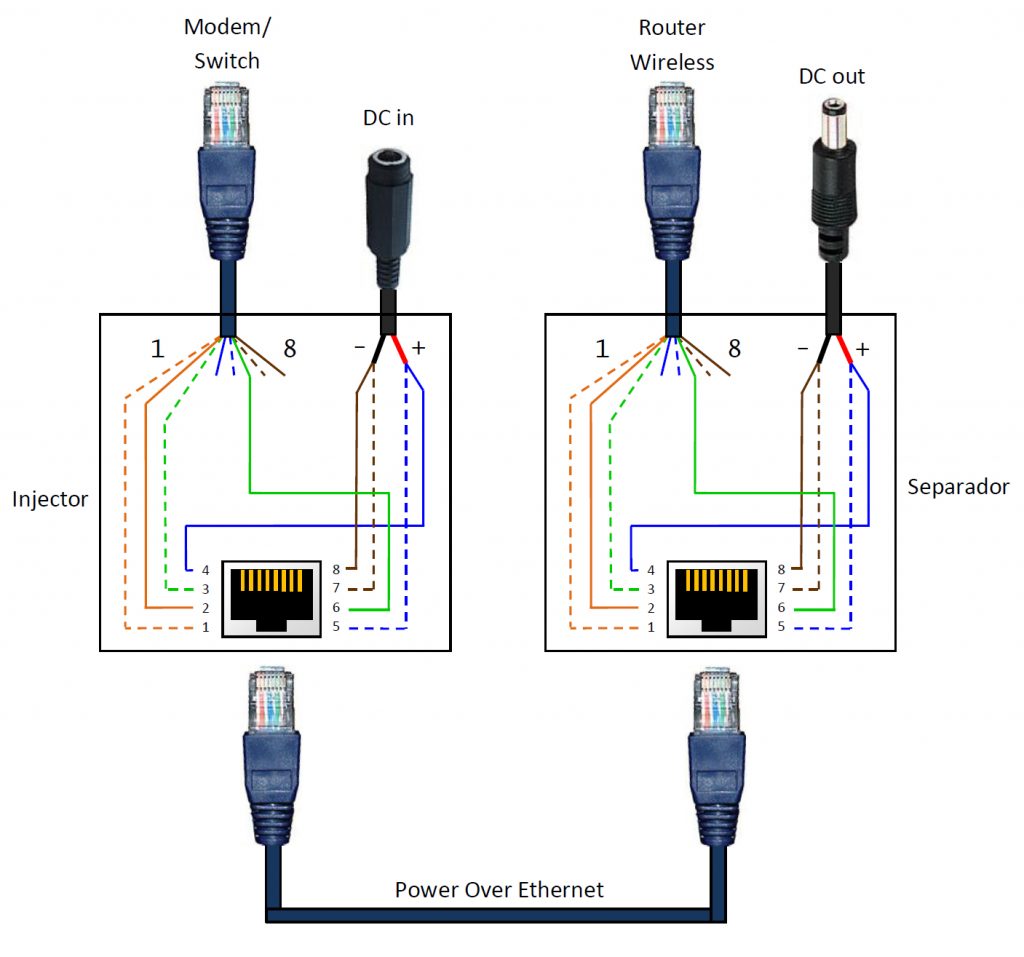
The diagram is usually divided into two sections, the power side and the data side. On the power side, the diagram typically shows the power cable and the connections for the power source. On the data side, the diagram shows the connections for the camera and the signal cable.

Ip Camera Pinout Wiring Diagram Circuit Diagram
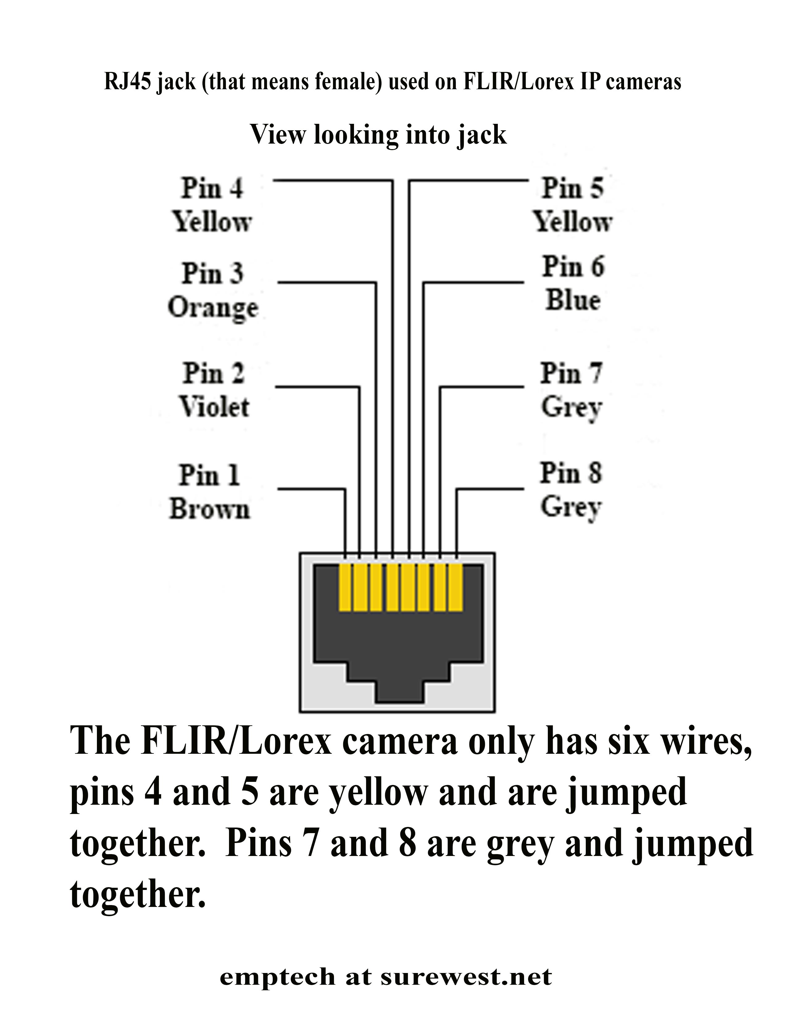
Info. VIP Vision PTZ cameras use TIA568B on the Female RJ-45 connector. VIP Vision IP Cameras use a specific wiring method with 6 wires, actual configuration varies between model, both variants are listed below. IPC Wiring Diagram - Type B (Actual Configuration may vary based on model) Cable Colour. RJ45 Pin Position.

Ip Camera Pinout Wiring Diagram lupon.gov.ph
20 Share 205 views 1 day ago 27 products Welcome to our in-depth guide on IP camera wiring! In this comprehensive tutorial, we take you through the step-by-step process of setting up your.
Ip Camera Wiring Diagram Cadician's Blog
What is the RJ-45 pin out for a Dahua camera (HFW 2831 and HFW 5242) Both IP cameras should be the same. It appears that that each CAT 5/6 pair is tied together as indicated in the below diagram. Pins 1/2 are POE minus with pins 3/6 a POE plus. i.e. pin out also confirmed with CAT 5/6 cable tester. What is confusing is that normally data RX is.
Ip camera pinout wiring diagram lasopapretty
Network wiring diagrams are used to wire IP cameras to a network. They show you how to connect your camera to a router, switch, or other network device. The diagrams will also include diagrams of the cables and connectors that you need to use to connect the camera to the network.
Poe ip camera wiring diagram primalasem
That's because the pinout diagram for Uniview is identical to the T-568B Ethernet wiring. So to get your Uniview camera terminated, you're going to line the colors up exactly the same way you would line them up for a standard Ethernet cable: orange stripe, orange, green stripe, blue, blue stripe, green, brown stripe, and brown.

Ip Camera Pinout Wiring Diagram lupon.gov.ph
X-Security or Dahua Pinout Wiring Diagram. Many X-Security and Dahua IP cameras may have a pinout diagram like this. On the left side is the RJ45 pinout (T-568B) and the right side is the PoE pinout of the IP camera (color coded wiring diagram). The connection is as shown in the illustration. For example, the gray wire goes to pin 8, brown to.